
Applications
 Part of the Oxford Instruments Group
Expand
Collapse
Part of the Oxford Instruments Group
Tutorials
Published: 01 Oct 2013 · Last updated: 10 Feb 2021
Tags: imagesegmentationandobjectdetection
Using the Contour Surface
The Contour Surface allows you to extract a 3D object by manually drawing the object contours on 2D slices while focusing on specific details. You can employ the Contour Surface method whenever automatic surface segmentation does not yield individual structures in a satisfying way (e.g. touching cells in confocal microscopy, complex tissue recorded by transmission microscopy).
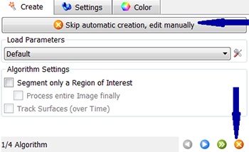
To start the Contour surface creation, you have to cancel the Surface creation wizard. You can do that either by clicking on the Cancel button or by selecting the Skip automatic creation, go to manual editing button.
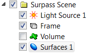
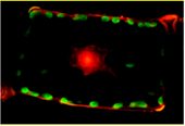
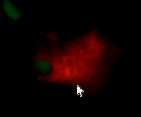
The creation wizard is halted and Draw Tab is automatically opened. In the viewing area, a drawing plane is displayed. To provide an unobstructed slice view, switch off the Volume rendering.
In order to get the required view, it may be necessary to re-slice the image data in a different orientation. Under the Board tab, orientation options allow you to slice data in any chosen orientation: YZ, XZ or XY.

When a slice orientation has been chosen, there are several ways to move between slices. You can drag the slider handle, use the up/down arrow keys or enter the slice number in the numerical field.

Before starting with the first contour line, switch the pointer from the Navigate to Select mode and adjust the position of the drawing plane. In the contour line creation method, there are two different modes: Active and Inactive. The main function of the Active mode is to create a contour line. In the Inactive mode, the existing contour lines can be modified or deleted. You can select the respective mode by using the Draw button 
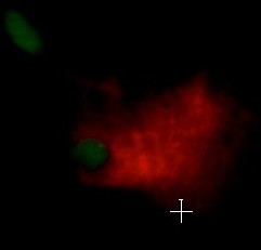
The pointer’s appearance on the screen depends on the selected drawing mode. The symbol on the screen changes from an arrow in the Inactive mode to a cross in the Active mode.
Under the Mode tab, several drawing mode tools are provided, allowing you to select areas in the current slice for contour line drawing Click on a tool icon activates a drawing tool.

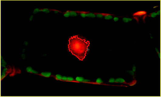
Click: Clicking within the image inserts a point, vertices. Successive vertices are connected with a straight-line segment.
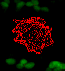
Time: Click once on the contour and then move the mouse along the contour. The number of vertices depends on the time interval (ms), specified in the corresponding field.
Distance: Click once on the contour and then simply move the mouse along the contour. The number of vertices depends on the specified distance interval. This drawing style is recommended if the structure is smooth.
Circle: The Circle tool always inserts a circular contour line. The cursor position indicates the centre of the contour line. The number of contour vertices to be inserted and the circle radius depend on the specified values. Alternatively, you can use the mouse wheel to alter the circle radius.
Isoline: The Isoline drawing mode detects the uniform intensity value under the mouse pointer and creates the largest connected area that contains all iso-value points. The current intensity value is displayed in the parameter field.
Magic wand: The Magic wand tool creates a contour line by selecting the largest connected area that contains the maximum intensity voxels and all voxels within a user-defined tolerance range. The Tolerance range defines the tool's sensitivity; the higher value you set then wider image area that is selected.
You can draw as many contours on a plane as required. Repeat the process until the contours are created for all slices. Under the Board tab, you can adjust the Visibility of the previously drawn contour lines.
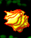
When you are satisfied with the created contour lines positions, click on the Create Surface button  to create a surface between the previously drawn contours.
Take a look at our related assets below...

© Oxford Instruments 2026