Applications
 Part of the Oxford Instruments Group
Expand
Collapse
 Part of the Oxford Instruments Group
High resolution imaging of large specimens which are larger than a field of view of a microscope has become more and more popular in recent years together with the rapid development of sample clearing techniques. The common imaging approach requires collecting multiple adjacent 3D blocks of image data by moving motorized microscope stage precisely step by step to cover the entire specimen and subsequent stitching of the data blocks into one image.
Imaris Stitcher is designed for automated alignment of overlapping 2D or 3D image tiles. The software gets microscope stage coordinates directly from image metadata so that native positions of tiles are loaded as stored by the microscope. If positions are not available Imaris Stitcher provides a user interface to arrange tiles in a grid layout or to manually position tiles, but its real power is rooted in the alignment algorithm which corrects for both systematic and nonsystematic errors arising during acquisition. Systematic errors typically arise from misalignment of the camera relative to the microscope stage axes. Nonsystematic errors arise from imprecisions in the motorized positioning of the microscope stage. The following paragraphs describe both types of problems and the approach that Imaris Stitcher takes to produce precise alignments of overlapping image tiles.
Rotation of camera versus microscope stage axes
Microscope stage positioning is not perfect. When a microscope repositions its stage relative to the field of view of its camera it generally doesn’t manage to move the stage exactly to the desired position. Suppose a microscope “wants” to translate its stage along the X-axis of the camera to capture two adjacent fields of view. That would be a simple task if the camera-X-axis was perfectly aligned with the stage-X-axis. The microscope could take the stage-X-axis as a proxy for the camera-X-axis. It would just need to drive its stage along the stage-X-axis and it would automatically drive the field of view along the camera-X-axis. In real life, in most commercial and home-built microscopes this situation is not perfect - the camera-X-axis is not exactly aligned with the stage-X-axis. In this case when the microscope “wants” to drive the stage along the X-axis of the camera, it actually drives the stage somewhat along the Y-axis too. This produces scenarios shown in the following figure (camera-axes depicted in green, stage axes depicted in red):
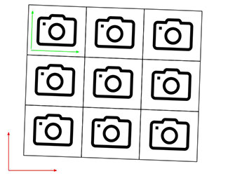
Microscope “wants” to capture these fields of view
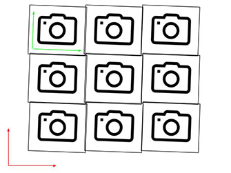
Microscope captures these fields of view
In many microscopes the rotational misalignment of the camera relative to the stage axes is less than 2 degrees and sometimes it is less than 0.5 degrees. While this misalignment may seem very small, a 0.5 degree rotation leads to 8 pixels offset in the Y-direction when the stage is translated 1000 pixels in the X-direction. Even a 0.1 degree error leads to 2 pixels offset in the Y-direction when the stage is translated 1000 pixels along X.
Distance Imprecisions
When a microscope moves the stage there is a mechanical imprecision in the distance that the stage actually moves. Suppose the microscope “wants” to move the stage 100 micrometers it might end up moving the stage by 99.8 micrometers. This produces scenarios as follows (exaggerated):
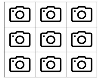
Microscope “wants” to capture these fields of view
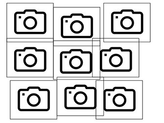
Microscope captures these fields of view
Both types of errors in positioning fields of view are seen together when a microscope is used to assemble a larger field of view from many small fields of view.
Acquisition of Overlapping Regions allows Alignment based on Image Content
In the light of the described positioning problems a typical approach to assemble large fields of view from multiple small fields of view is to acquire the small fields of view with some overlap and then to reposition images in such a way that their content optimally matches in the overlapping regions.
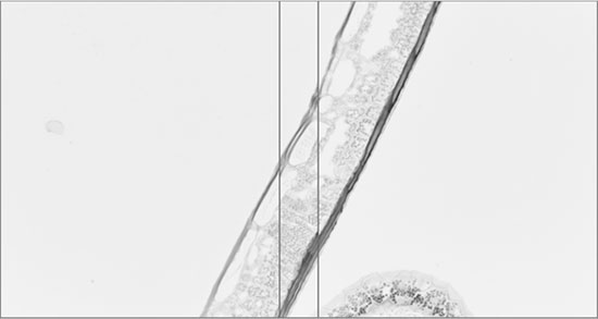
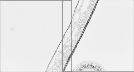
The image below shows two overlapping fields of view acquired on a typical microscope. It is clearly visible that the fields of view can be aligned based on the image content in the overlapping region.
After alignment the image content matches well:
Reliability Problems in Image based Alignment
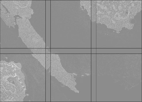
Aligning images based on their image content is not always possible or easy. For example when two overlapping regions have very little content it can be impossible to tell how they should be positioned. Or when the overlapping region depicts a structure like a straight line that is translationally invariant it is not possible to derive a precise position of the overlapping images. To give another example, when the imaged structure has a complex periodic signal, multiple possible positions could be good candidates from the point of view of an image based alignment method.
The following image shows six fields of view of which some have content that has good information to reposition images while other overlapping regions have very poor information to do repositioning.
Camera Rotation can be robustly modeled from a small subset of overlapping images
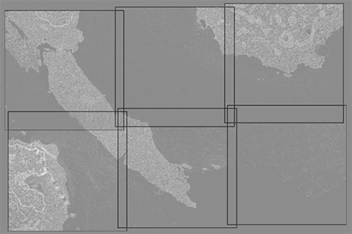
It is interesting to note that the rotation is a global operation that requires just a single value, the angle of the rotation, to “undo” all rotational errors. This value can be robustly estimated from just a few pairs of overlapping images and it can then be used to reposition all images, even those that do not have image content which provides a reliable positional estimate. In the scenario above the lower-right-hand image is not easily positioned using image content based positioning. However, since the camera rotation can be robustly estimated from other overlapping image pairs also the lower-right-hand image can be repositioned by undoing the camera rotation to yield the following image positions that no longer suffer from the camera-versus-stage-axes-rotation.
Imaris Stitcher Alignment Algorithm
Imaris Stitcher performs the following steps to align overlapping images
Grid layout positioning with overlaps requires scaling
In situations where the user specifies a grid layout for all image tiles instead of using tile positions stored by the microscope, another source of systematic error may arise. If the user specifies a “wrong” overlap percentage of neighbouring tiles this effectively amounts to a scaling of the X or Y axis of the “stage” relative to the X or Y axis of the camera. To compensate not just for camera rotations but also for this systematic scaling, Imaris Stitcher estimates both a camera rotation and scale factors for the X and Y axis independently (in step 3 of the algorithm).
Manually positioned tiles are exceptions
The detection of untrustworthy repositionings as described above compares each proposed residual pairwise translation to the “typical” residual pairwise translations. An exception applies when a user has manually repositioned a tile. In this case it is quite possible or even likely that the manually positioned tile will require a “large” repositioning and the comparison to “typical” is not performed.
Alignment Examples
Here are some examples “before” and “after” alignment. In some of them the rotational camera modeling is very clearly visible.
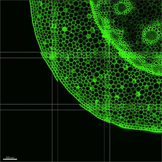
Before alignment
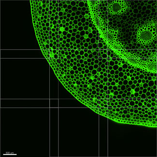
After alignment
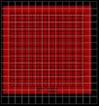
Before alignment
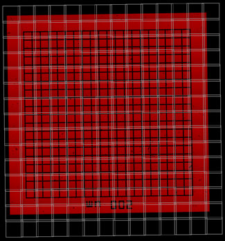
After alignment
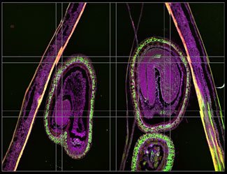
Before alignment
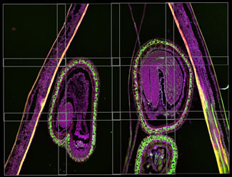
After alignment
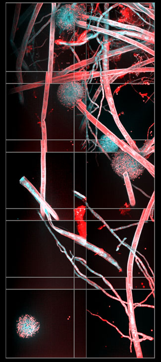
Before alignment
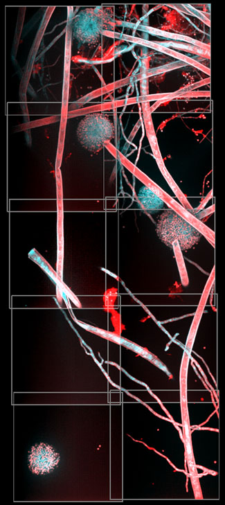
After alignment
Literature
[Preibisch 2009] Stephan Preibisch, Stephan Saalfeld and Pavel Tomancak (2009) Globally Optimal Stitching of Tiled 3D Microscopic Image Acquisitions Bioinformatics 2009, 25(11), 1463-1465.
