Applications
 Part of the Oxford Instruments Group
Expand
Collapse
Part of the Oxford Instruments Group
Andor Academy
Published: 10 Feb 2021 · Last updated: 10 Feb 2021
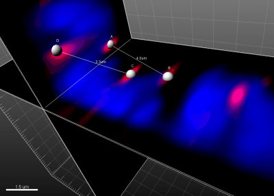
Within the MeasurementPro module Imaris offers tools for making quick, manual distance measurements directly on your 3D image. By using Measurement Points you can easily obtain the distance between two structures or between arbitrary locations by interactively specifying those positions simply using mouse clicks. Measurement points can be placed anywhere within your 3D volume data; either on Surpass objects (Spots, Surfaces, Cell, Filaments, Ortho and Oblique Slicers) or in the volume rendered image to measure distances amongst non-segmented structures of interest.
You could imagine that placing points at the correct depth within a 3D image is a cumbersome task. However, Imaris uses an AutoDepth algorithm to automatically position the points at the correct depth within the 3D image. Depending on your selection the placement of a point is determined by either: 1) the most intense voxel of all channels directly underneath the cursor, 2) the most intense voxel of a specific channel directly underneath the cursor or 3) previously created solid objects. (Surface, Spot, Filament and Cell objects as well as Ortho and Oblique Slicers are all considered “solid objects”.)
The first two options are applicable if you wish to insert Measurement Points in a volume rendered data set. When measuring distances from, for example, a Surface to a Filament then the solid Objects option is appropriate. It is also possible to measure distances between solid objects and points of interest within (non-segmented) volume rendered data.
Start a new set of measurements by adding a Measurement Points object to your current Surpass Scene
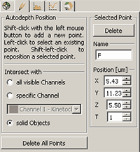
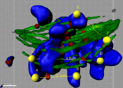
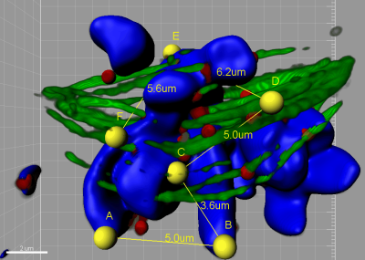
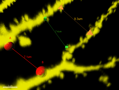
While on the Edit tab (Fig 1) and in Select mode, add a new point by holding Shift and clicking the left mouse button at the location of your choice within the 3D image. The new point will either be placed at the correct depth determined by either voxel intensities or by the presence of a solid object underneath the cursor as described above. After placing a second point a new line connecting the two points is created. Distances can be calculated 2 points at a time (Lines; Fig 2) or by consecutively connecting all points (Polygon; Fig 3). This option is found on the Measurement Points Settings tab.
For easy editing, points can be moved after placement. The point must first be selected (left mouse click) and then the correct numerical values can be entered into the X, Y, Z fields.A point can also be moved by first selecting it and then using Shift + left mouse click to place it in another position. All of these features are found on the Edit tab, where you can also adjust the name of the point or delete it. Deleting all points is also an option found on the Edit Tab.
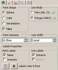
To change how points are displayed in the 3D Surpass view and to customize the display of the information provided for line measurements, use the options found on the Settings tab (Fig 5).
Here, you can choose from three different point shapes (tetrahedron, cube, or sphere; Fig 4). You can also change the line width and color. Options on the Color tab allow you to assign a different color for each unconnected line.
Once a line is created, Imaris displays the intensity of each voxel along the line. To display the Intensity Profiles along the lines click on the Histogram tab (Fig 6).
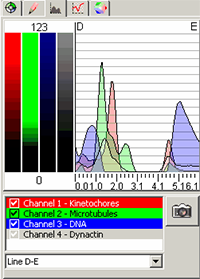
The x-axis of the histogram represents the length of the line, while on the left-hand side of the histogram, the channel(s) intensity range is displayed. Below the histogram, you can find the channel and line selection. Here you select the channels and lines that should be displayed. The histogram can display any or all measurement pairs. Clicking on the Snapshot button creates a still image (.tiff) of the histogram and intensity range(s).
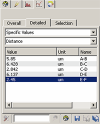
Under the Statistical tab (Fig 7), the results of each line measurement are shown.
You may be wondering how to place a point within a specific plane of the image when it lacks a solid object or high intensity voxel in that particular position. Ortho and Oblique slicers are ideally suited for this occasion because they can be placed at a specific plane and are solid Objects (Fig 8). First, insert a new Slicer and position it at a plane where you wish to place a new Measurement Point. Then, switch to a Measurement Points object, select solid Objects and place a new point on the Slicer.

© Oxford Instruments 2026