Hardware Solutions
Applications
 Part of the Oxford Instruments Group
Imaris 10.1 brings native machine learning segmentation to Imaris. Previously machine learning segmentation was possible via the open source software Labkit [Labkit2022]. Now it is seamlessly possible within Imaris itself. And it’s fast!
Machine learning segmentation is one step in the Surfaces Creation Wizard. In this step you can train a machine learning system to segment the image by simply painting some foreground pixels and some background pixels and letting the machine learning system infer the rules that fit your painting. This is a very intuitive and easy way to set up segmentation that is significantly more versatile than a simple threshold. For example, machine learning segmentation can be trained to fill holes inside objects when the holes are small, or it can be trained to detect thin elongated structures or round structures.
The workflow to set up the machine learning segmentation is about as simple as it gets. You see with your eyes where there is “foreground” in the image and you just paint on that with the foreground color. Similarly you paint on some background with the background color. Then you ask the machine learning system to show you what it can predict for the rest of the image from what you’ve shown it. If it doesn’t get it right, you paint some more foreground or background in some of the places where the classifier got it wrong and then you ask it to show you again what it can predict. That’s the whole workflow. All you need to know is where you want foreground and where you want background.
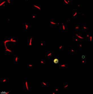
| Training Round | Paint strokes for training | Preview after "Train and Predict" |
| 1 |  |
 |
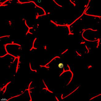
| 2 |  |
 |
The machine learning segmentation attempts to infer rules that fit your painting. The way you paint has an influence on how the classifier can learn. Here are a few suggestions:
Of course a machine learning system has some technical details that affect how it works. On a coarse level you may want to know that it is a Gradient Boosted Trees classifier [Friedman 2001]. You might want to know that the classifier receives Derivative of Gaussian features up to second order computed at a wide range of scales [Koenderink 1987], specifically 1,2,4,8,16, and 32 times the sigma specified in the user interface. You might want to know the hyperparameters of the decision trees. And more and more. But in a sense knowing all those technical details is counter to the ease of use of the workflow. The tool is so easy to use. We have put significant effort into setting up all the technical details of the system in such a way that they will just work for a large range of situations. You don’t have to care about them.
Slicers in Imaris have an adjustable thickness. No need to stick with the single slice that comes out of the microscope. You can improve visualization by giving the slice a thickness that lets you see the relevant biology. You might for example want to make it thicker than a single nucleus or thicker than the diameter of a blood vessel. When you work with machine learning segmentation you can paint on thick slicers too because Imaris automatically selects the right training data from your paint stroke. This makes painting very efficient. Try it.
When Imaris renders an image onto a thick slicer it does a maximum intensity projection. That means, only the maximum intensity voxels inside the thick slicer get rendered to the screen. When you paint on the thick slicer it is this set of maximum intensity voxels within the slicer that you paint on. Even if the thick slicer is thicker than a bright structure you paint on, the voxels that Imaris selects for training are the bright voxels you painted on. Imaris paints only those voxels you see on the display. It’s WYSIWYG. What you see is what you get.
One of the things you may want to do is to apply the same classifier to multiple images. The trained classifier and the corresponding training data are stored as part of the Surfaces creation parameters, which can be then used to run batch processing or be opened on a new image to continue training.
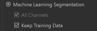
You can store a classifier in Favorite Creation Parameters and use it for another image. When you do so you get the option to continue training on the new image while keeping the training data from the first by checking the “Keep Training Data” checkbox.
If you choose “keep training data”, add more training data for the second image and then save the classifier it will then contain its previous training data plus those from the new image.
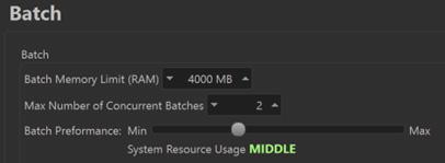
In Imaris 10.1 you can influence the speed at which batch processing runs by choosing one of four performance settings in the Batch section of the Preferences.
Starting with version 10.1 Imaris opens 2D images in a 2D mode. That means the viewers keep the image in the plane of the display. The handles for interacting with objects are 2D handles. Some things that don’t make sense in 2D are not available when a 2D image is opened. And last but not least, statistics values are computed specifically for 2D images.
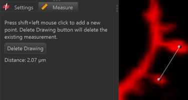
On OrthoSlicer and ObliqueSlicer you can do length measurements by going to the “Measure” tab.
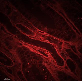
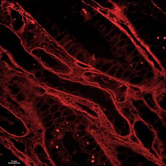
Pseudo flat field correction is available as an image processing function in Imaris to correct for systematic intensity variations across the field of view that arise from properties of the acquisition system. A typical example is a decrease of intensities toward the edges of the field of view.
The pseudo flat field correction function uses a Gaussian Filter of user-specified width to estimate a flatfield F from the original image I. It also optionally estimates a dark field D that is otherwise defaulted to 0. With these, the corrected image C can be computed using the formula C= (I−D)×m/(F−D) where m is the image averaged value of F-D.
| 13 Bugs Fixed in Imaris 10.1 | |
| 6247 | Improve Speed of Median Filter - unable to complete process |
| 12380 | Cannot move Z-axis cross-hair in Surpass 'section' view after changing Z-voxel in image properties |
| 12459 | Scalebar is incorrect using "Orthogonal" view (not perspective) |
| 12792 | oib file stage coordinate not recognized |
| 13181 | Exported values for Number of Spots Inside do not match table on statistics tab |
| 13334 | Contour surface with YZ surface cause Imaris crash |
| 13420 | Error: Labkit Segmentation Failed after Fiji update |
| 13531 | Classify Spines XT crashes Imaris if spines or filaments have been manually edited |
| 13547 | Crash between step Seed Points Classification' and 'Segment Classification' |
| 13568 | Imaris Crashes when a created Contour surface saves when SpatialStats is turned ON |
| 13587 | Surface filtered out from using a specific seed point threshold at specific timepoints 16 and 47 |
| 13618 | ND2 File Format is not recognized properly |
| 13645 | Creating a New filament object within XT, but never sending to Imaris will cause Imaris to crash |
| 33 Bugs fixed since Imaris 10.1.0 | |
| 13383 | CZI 3D time lapse with multiple fields is not converting properly in Imaris 99 |
| 13770 | Imaris 10.1 not calculating statistics correctly in 2D mode |
| 12378 | Spots Statistic 'Intensity Sum of Square' not in statistics manual |
| 13553 | Traditional TIFF series crash when you set the settings to use "F-Split" in Imaris10 |
| 13729 | Free rotate for 2D is not working |
| 13416 | Imaris File Converter (and Arena) unable to correctly convert Abberior multi-dataset images into IMS |
| 13722 | Recompute Filaments does not display seed points and segments with the color of their class |
| 13727 | Batch with Machine Learning Segmentation hangs at 6% |
| 13740 | If Creation Parameters on 2D datasets are saved with pre 10.1, still get the old 3D statistics on 10.1 |
| 13745 | ND2 Files Channel Display Does Not Display/Adjust Correctly |
| 13667 | Pixel Classification results differ heavily on Windows and Mac |
| 13712 | Machine Learning Segmentation does not work for Batch with Image Processing |
| 13716 | Cut Surface 2D creates strange new surfaces |
| 13720 | Single channel flickering, duplication artifacts and unresponsiveness in this multi-channeled image |
| 13734 | If the Cut option is used occasionally an error message appears: Could not cut surfaces at the specific location |
| 13749 | Volume displays 4 channels only |
| 13754 | This dataset can't show the "Overlapped" stats |
| 13775 | adding timepoint to 2D image and running pixel classifier is failing in Imaris 10.1 |
| 13788 | 2D surface morphological splitting is not working properly in 10.1 and 10.0 |
| 13791 | Batch does not create objects with pixel classification |
| 13792 | Pixel Clasification does not work with Multi Image |
| 13796 | Threshold Not Shown in 2D Batch Surface Interface |
| 13585 | Not all chanels on all tiles imported from CZI |
| 13778 | Error when entering Pixels Classification step in Surfaces for files on a path with Umlaute (special characters) |
| 13711 | Class color not always used in seed point and segment training step |
| 13721 | Recompute Filaments gives very different result |
| 13742 | Object view of Vantage can’t be shown in 2D dataset |
| 13653 | Surfaces generated on 2D image can NOT calculate the shortest distance statistic. |
| 13717 | For some circular 2D objects a circularity of 0 is reported |
| 13718 | If a 3D image is turned into 2D (through Cropping, Project to 2D XT or swap Time and Z) the statistics are still calculated for 3D image |
| 13738 | Image is not visible after resampling 3D with Z=1 and saving |
| 13748 | 2D BoundingBoxOO is wrong in Imaris 10.1 |
| 13772 | Imaris 10.1 pixel classified surface fails to complete when file size is greater than 200GB |
© Oxford Instruments 2024